GPIO
(Note: image sourced from here)

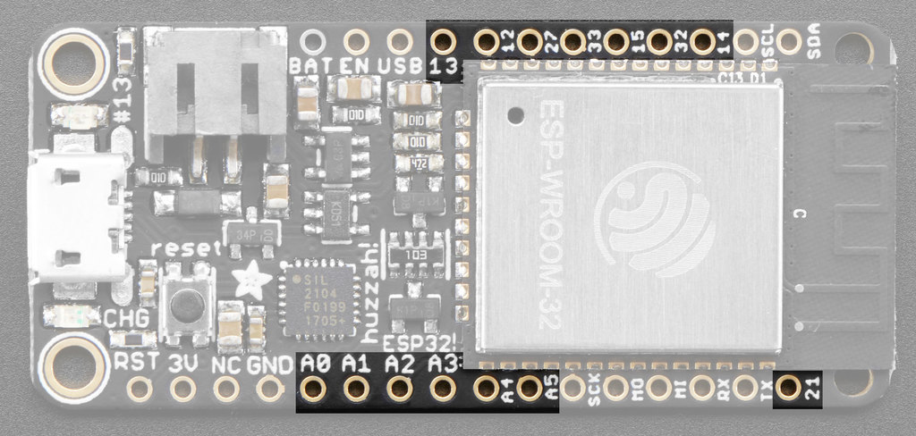
The ESP32 has a variety of pins, each of which perform different functions. For example, last week we looked at 3V and GND, pins which give us access to the power and ground on the device respectively.
The photo above highlights a number of pins that do not have a single function and are instead referred to as General Purpose Input/Output (or GPIO) pins. Note: it is normal to have to consult a datasheet in order to identify pin functionality.
Top row
- 13: GPIO
13, also connected to the on-board LED - 12: GPIO
12 - 27: GPIO
27 - 33: GPIO
33 - 15: GPIO
15 - 32: GPIO
32 - 14: GPIO
14
Bottom row
- A0: analog output DAC2 or GPIO
26 - A1: analog output DAC1 or GPIO
25 - A2: GPIO
34+ - A3: GPIO
39+ - A4: GPIO
36+ - A5: GPIO
4 - 21: GPIO
21
Note: + denotes input only
Electrical Signals
In electronics a signal is a time-varying quantity which conveys information. The quantity that is varying over time is typically voltage or current. Physical Computing involves interfacing two types of electrical signals: digital and analog.
Digital Signals
(Note: image sourced from here)

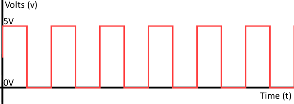
A digital signal is comprised of a sequence of discrete values. We typically think of these values as binary, or sequences of 1 and 0, and associate them with computers. There are, however, a variety of equivalent ways to refer to this same alternation:
| V+ | GND |
|---|---|
| HIGH | LOW |
| 1 | 0 |
| True | False |
| On | Off |
To date we have exclusively worked with digital inputs and outputs: a button (input) is either connected (on) or disconnected (off); an LED (output) is either illuminated (on) or dark (off).
Analog Signals
(Note: image sourced from here)

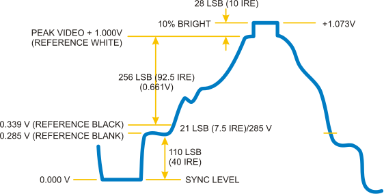
An analog signal is comprised of a signal varying value any point within a given range. The photo above, representing the composite video signal from an RCA plug, is one example of an analog signal. Generally people refer to phenomena in the "real world" as analog: light level, temperature, weight, etc.
Note: ESP32 pins which begin with an A are analog capable pins.