Transistors
Note: props to this fantastic article
Transistors are three pin components capable of amplifying or switching signals. In Physical Computing we typically use them to control high voltage devices (like motors, lights, or solenoids) by quickly toggling a pin between HIGH and LOW (i.e. PWM).
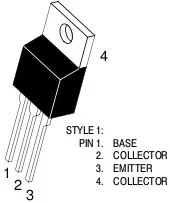
While there are a variety of different types of transistors, we will focus on the TIP120, a pinout for which can be found below:

- Base -> Control
- Collector -> Input
- Emitter -> Output
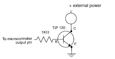
More specifically, transistors are based on the following phenomena: a small current flowing between the base (B) and emitter (E) causes a larger current to flow between the collector (C) and emitter (E).

ESP32 + TIP120
Schematic

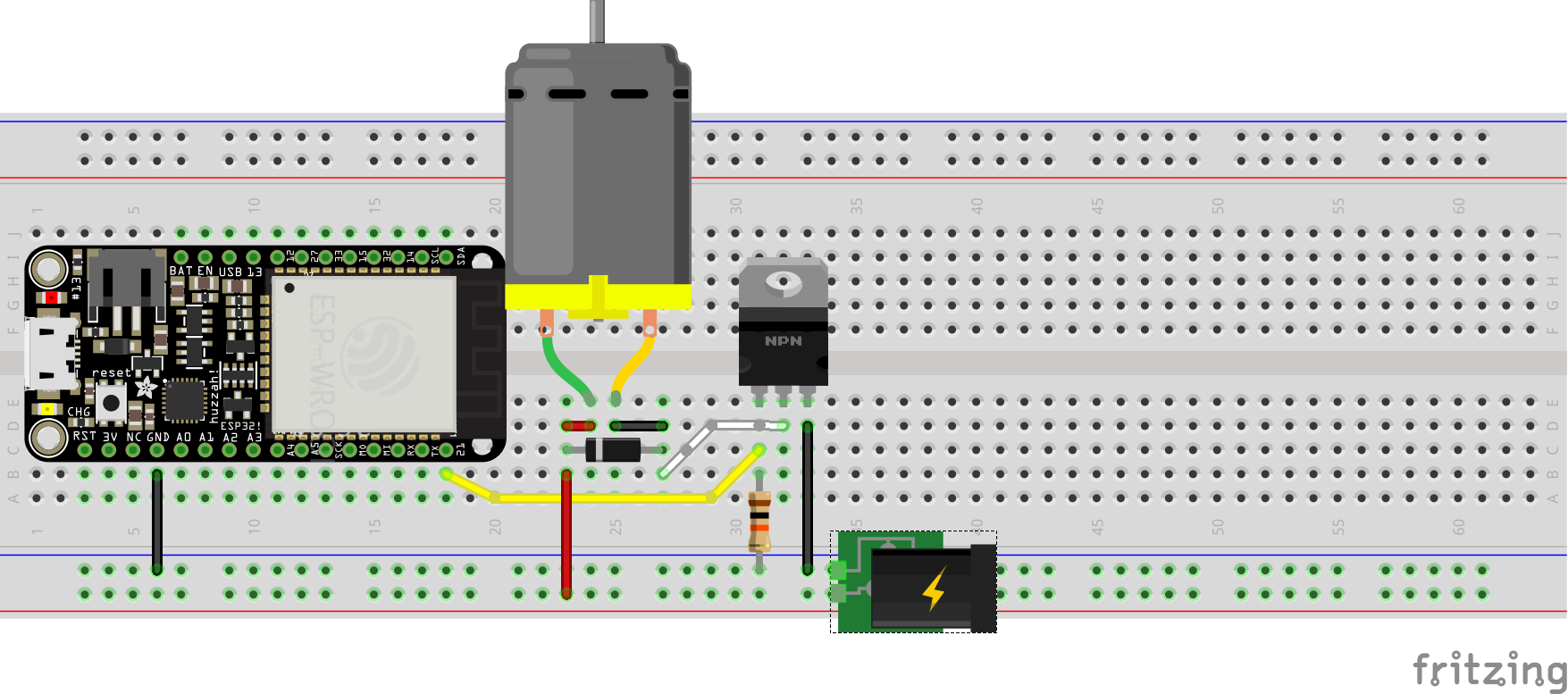
Hookup Pattern

After wiring up a TIP120, diode, resistor, and motor (as shown above), one could test controlling the motor with the following:
- import
PinandPWMfrommachine:from machine import Pin, PWM - create a
PWMobject and store it atpwm21:pwm21 = PWM(Pin(21), freq=20000, duty=0) - set the
duty cycleto 50%:pwm21.duty(512) - set the
duty cycleto 100%:pwm21.duty(1023) - stop the motor:
pwm21.duty(0) - turn off
PWMmode on pin:pwm21.deinit() Ctl-ACtl-\to exit
TIP120 as Digital Switch
When the ESP32 sends a HIGH signal to the TIP120 Base the transistor switches, connecting the Collector and Emitter pins. If C and E are connected the circuit is closed (or complete), allowing current to travel to the motor which causes it to spin.
When the ESP32 sends a LOW signal to the TIP120 Base the transistor disconnects the Collector and Emitter. This results in an open (or incomplete) circuit and the motor stops spinning.
The speed (rate of rotation) of the motor is controlled by how long the PWM pin is HIGH compared to the length of a single period (LOW plus HIGH time), otherwise known as the duty cycle.
Note: the exact same wiring pattern used to control a motor (see schematic above) can be used to control a large light or solenoid, one simply needs to remove the motor and replace with one of the other actuators. Certain solenoids will require changes to software to reflect their physical properties.
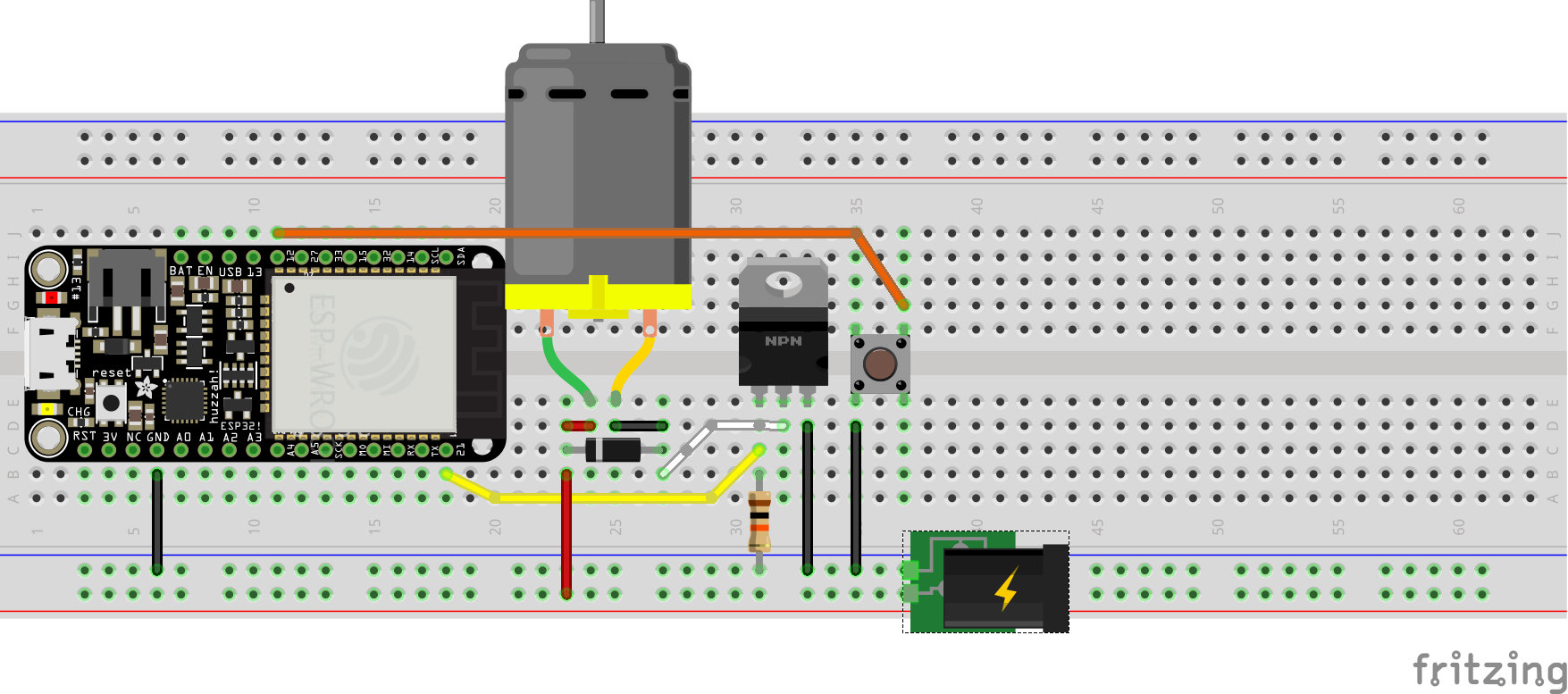
Hookup Pattern

In the next example a button, added to pin 12, controls whether the motor spins or not.
For Example
# digital in to pwm out

from machine import ADC, Pin, PWM
from time import sleep_ms

motorPin = Pin(21)
pwm = PWM(motorPin, freq=20000, duty=0)

button = Pin(12, Pin.IN, Pin.PULL_UP)

while True:
    if not button.value():
        print("Spin")
        pwm.duty(1023)
    else:
        print("Stop")
        pwm.duty(0)
    sleep_ms(20)